Relay Co-Ordination in Power And Grid Sub Stations
The main function of a power substation is ac voltage conversion with safe power supply .This safe supply is dealt by the name of protection or more elaborately
Power System Protection.The most important cause of accidents and failure of power transformers is snapping of conductors caused by persistent faults on supply lines.
Snappings can be averted if this faulty part of supply line is disconnected from supply end by VCB before the snapping takes place.Programming is art of managing complexity.
A relay which is programmable switch is the core of protection and if programmed properlyclears the fault in a preset time by disconnecting only the faulty portion of line.
In a power substation assuming the voltage as constant E/F(Earth Fault) relays which are basically over current distance relays take controll input neutral and a common point 3 CTs connected in three phases.
An imbalance of neutral of CT exceeding a preset value is fed to relay and the relay takes logial decission to give output to trip coil of VCB to disconnect the shortest faulty portion of supply or transmission line. These relays give ditance protection
upto a prespecified distance determined by minimum value of current on which the relay will activate. As the length of line increase its impedence increases correspondingly and the fault current will not be enough to activate the relay and tripping circuit.
Beyond this distance the relay will not give tripping command. Or its behaviour will not be predictable.The falure of E/F relay of 33KV jhajha feeder in G/S/S in Malai pur Jamui was due to long distance (40km) between pss(sono)and GSS,insufficient earthing
due to rocky soil and non provision of LILO in Gidhar and Jhaja PSS causing death of 6 children in village bChandra of village and tail end pss at Sono.
In case of unbalancing of current beyond a specified limit which in general is found in case of faults the relay close the trip circuits and the dc current magnetises the trip coil of VCB and draw the plunger to disconnect cotacts
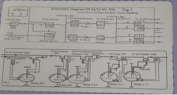
disconnecting the faulty part of lines. Fig ! is a lay out of a PSS and fig2 shows connections of VCB and earth fault relays. Time setting and co ordination of relays in different levels of protective
switch gears have achieved importance due to expanding capability,capacity,complexity of power systemand energy consumption (700mw to 3500 MW.in last 3 to 4 years in our state.
The transmission capacity of power equipments have increased tremendously by eliminating constrants .If VCBs are not provided and their relays set amd matched and co ordinated properly for different voltage levels of supply there would
be uncertainty of protection and loss and damage of equipments,lives and properties,credibility and reliability.
In our Power Sub Stations now a days Vaccum Circuit Breakers are generally used. In modern power system Hybrid Switch Gears like Gas Insulated Vaccum Circuit Breakers (SF6 sulpher hexa floride)are in
process of being introduced that have advantages of taking less space and being compact in shape.
The main advantage of vaccum circuit breaker is the short arc quenching or extinction time in comparision to other conventional Oil filled circuit breaker(OCB). The rapid building up of dielectric strength after final arc extinction
is a unique advantage of a VCB. It is also superior to SF6 circuit breakers when compared to arc extinction time and season dependency.On very low (negative)temperature SF6 gas liquifies and manifests erratic behavior.In conventional oil circuit breakers the arc extinction time is about 3 to 7.5 cycles.ie 0.06 to 0.15 seconds.
In a VCB movable contacts are designed to travel 6 to 10 mm for breaking the circuit. The arching time depends also on the phase position of fault current where tripping circuit operates. If contacts of circuit breakers open on load There is an arc in the circuit breaker,established between the seperating contacts.
As long as this arc sustains in between the contacts the current through the circuit breaker is not interrupted because the arec itself is a conductive path of electricity.
As there is nothing to be ionised in the below(chamber)of contacts of VCB ,the interrupting((arching)time is theoritically 0.But due to ionisation of mettatic contacts and residual gases
(ideal vaccum is impossible) the interruption (flash over)time may be assumed as 0.025seconds for practical considerations which is the minimum time of interruption also generally fixed by manufacturers.
The fault current travels towards its source and affects all the VCB in its route. In order to achieve minimum outage of power only nearest VCB of sendind side from the point of fault should trip and in worst case if it fails then only VCB of upper level which play the role of second line of defence should operate because tripping of more upper VCB
will cause black out in large area which is against the sprit of OMS(outage management system). When a fault occurs all the relays in its path start to travel to cvlose their trip circuits.Relays set at long angular distance take longer time to close the DC trip switch.placed on rotating disk of relays.As soon as a relay having lowest travel distance causes to close its trip circuit ,its VCB trips.
The current in disconnected line becomes zero and the rest of relays in the route of fault move back to their original positions without tripping their VCBs. In numerical relays the same conditions are assimilated and programmed.
Let t1 and t2 be the time settings in seconds for E/F relays of feeder and group VCB respectively.
During the period of interruption (period of arching)in lower level VCB (receiving end VCB in this case 11KV feeder VCB) the flow of current in upper level of VCB(Source level in this case 11 kv group VCB) will simultaneously persist and if time setting t2 of upper level VCB is kept less than t1+0.025 seconds
,both VCB will trip.and cause outage of power in a vast area which is not a desirable feature in power system protection and supply. Similar will be the case as we go to upper and upper levelstowards source of supply in
in grid substations.Hence for reliability and quality power supply time settings of earth fault relays must be kept suitably co ordinated in increasing step of 0.025 seconds from lower to higher levels of VCBs.In view of the above facts the time setting of earth fault relays for 20% of full load currentsetting(Plug settin multiplier)may be done as given below.Keeping PMS less may lead to its malfunctioning due to unbalancing inload currents
switching surges or saturation of CTs during phase faults.
In order to have the co ordination of relays in different levels of supply (TMS(Time Multiplier Setting) of GSS and PSS for earth fault may be taken as follows.
| 220/132 KV GSS |
132/33 KV GSS
| 33/11 KV PSS |
| o.375 to 0.275 |
0.250 to 0.150 |
0.125 to 0.025 |
In 33/11 KV PSS
| VCB Positions |
E/F Settings Sec(TMS)
| O/C Settings Sec(TMS) |
| 33KV Feeder(Outgoing) |
0.150 |
0.160 |
| 33KV Transfer Bus |
0.150 |
0.160 |
| 33KV Group (LV side) |
0.175 |
0.185 |
| 132KV Transformer HV side Protection |
0.2 |
0.210 |
| 132KV Incoming |
0.225 |
0.235 |
| 33KV Outgoing (LILO) |
0.250 |
0.260 |
In 220/132KV G/S/S
| VCB Positions |
E/F Settings Sec(TMS)
| O/C Settings Sec(TMS) |
| 33 KV Out Going Feeder |
0.275 |
0.260 |
| 33KV Transfer Bus |
0.275 |
0.285 |
| 33KV Group(LV Side) |
0.300 |
0.310 |
| 132KV Transformer Protection(HV Side) |
0.325 |
0.335 |
| 132KV Incoming |
0.350 |
0.360 |
| 33KV Outgoing(LILO) |
0.375 |
0.385 |
It is to be noted that every E/F is associated with O/C(over current) in phases.If TMS of E/F and O/C relays are kept equal O/C relay will also operate simultaneously on E/F unnecessarily.
As the O/C relays fault is not so serious as compared to E/F the time setting of O/c O/C may be kept on higher side. The time setting of over current relays may be done at TMSoc= TMSef+0.010 seconds for respective VCB where TMSef and TMSoc are time setting in seconds for E/F and O/C relay respectively.This will eliminate the undesirable feature of simultaneous activation of both
E/F and O/C relays for any earth fault.
The relay settings of 220/132KV grid substations may be done also on above principle.
From a PSS the outgoing 33KV feeder (LILO)must be tapped before the incoming 33KV VCB ie the incoming and outgoing VCB in a PSS should not be in series.This arrangement will ammune(seperate)
one PSS from the fault in other's zone.
As a convention position of CT with respect to vcb is kept such that such that on disconnection of line by VCB the current in ct becomes zero but voltage of PT (Potential Transformer)is shown in voltmeter.
In other words when goiung in the direction of current we meet PT,VCBand and then CT.A metering unit may be positioned on th place of a PT. Improvement is a continuous process. in an age of continuous technological development
nothing can be set as ultimate standard.